Article: Hbbins 306
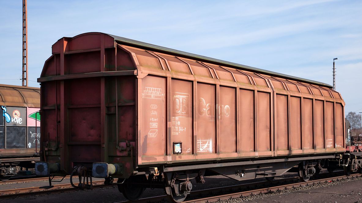
Freight wagon with two wheelsets and two-part aluminium sliding walls.By dispensing with lockable partitions, this covered freight wagon stands out thanks to its large load volume.
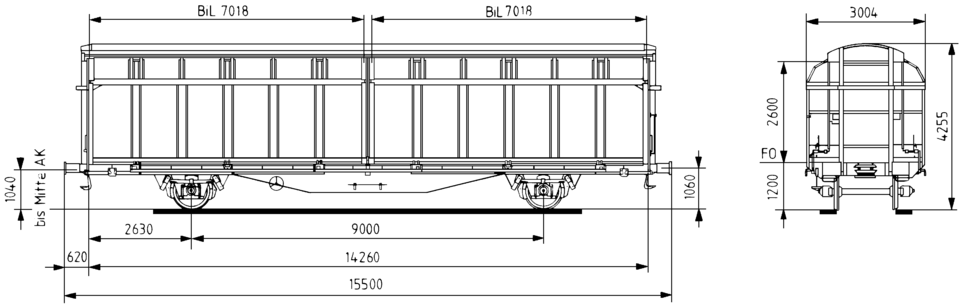
Please note: Type is similar to the wagon in the photo. For exact dimensions, please refer to the drawing and the data below.
The wagon is identical in construction to Hbbillns 304 and Hbbillns 305 and differs in the number of partitions.
Technical details
| Loading length (mm) | 14,236 |
| Loading width (mm) | 2,900 |
| Loading height (mm) | 2,400 |
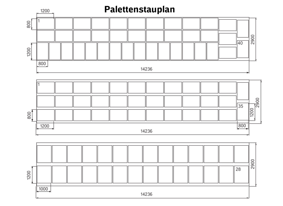
| Loading area (m2) | 41.3 |
| Average tare weight (kg) | 14,932 |
| Maximum speed (km/h) | 100 |
| International usability | RIV |
| Harmonisation/standardisation | UIC |
| Smallest radius of curvature (m) | 35 |
| First year of delivery or year of construction of the oldest wagons at this time | 1984 |
| Parking brake | With and without parking brake |
| Brake type | KE-GP |
| Number of brake cylinders (pcs.) | 1 |
| Brake cylinder diameter (mm) | 300 |
| Type of load-proportional braking | Two-stage, mechanical, to be changed over manually |
| Buffer type: end force (kN) | 590 |
| Buffer type: stroke (mm) | 105 |
| Buffer head dimensions (mm) | 450 x 340 |
| Automatic coupler | Prepared |
| Distributor valve type | KE 2adSL-D |
Individual data
| Side wall openings: width (mm) | 7,018 |
| Side wall openings: height (mm) | 2,600 |
| Running gear as per drawing | 1Fwg305.1.02.000.001 |
| Parabolic springs: stretched length (mm) | 1,200 |
| Parabolic springs: number of spring leaves | 4 + 1 |
| Parabolic springs: spring leaf width (mm) | 120 |
| Parabolic springs: spring height (mm) | 202 |
| Loading space to bottom edge of wagon body top chord (m3) | 105.0 |
| Loading space up to upper edge of transport guard (m3) | 98.5 |
| Clear ceiling height up to the first slope inward of sliding wall (mm) | 2,120 |
Load limits
Average tare weight = 14.9 t
With and without parking brake
| A | B | C | D | ||
|---|---|---|---|---|---|
| S | 17.0 t | 21.0 t | 26.0 t | 30.0 t | |
| 120 |
Additional information:
The wagon differs from Hbillns 302/303 freight wagons not only in terms of the increased length and width dimensions but also in terms of the sliding wall system, which is guided at the top and runs on rollers at the bottom. As with the predecessor types Hbillns 302/303, the sliding wall system allows the wall to be guided parallel to the vehicle body during the entire opening and closing process. The actuating rods for the sliding wall system are located on the end walls.
The underframe is a welded structure and consists of two continuous side solebars and crossbearers that connect the solebars and on which the forces from the floor and payload are transferred via floor beams. The floor consists of 45 mm thick pine planks and is approved for driving on with forklift trucks for a maximum load of 2.2 t per front wheel.
To secure the load, the wagons are equipped with
- 12 lashing rings that can be retracted into the wagon floor and
- 2 lashing rings on each end wall.
All data provided without any guarantee of correctness or completeness.
 Go
Go