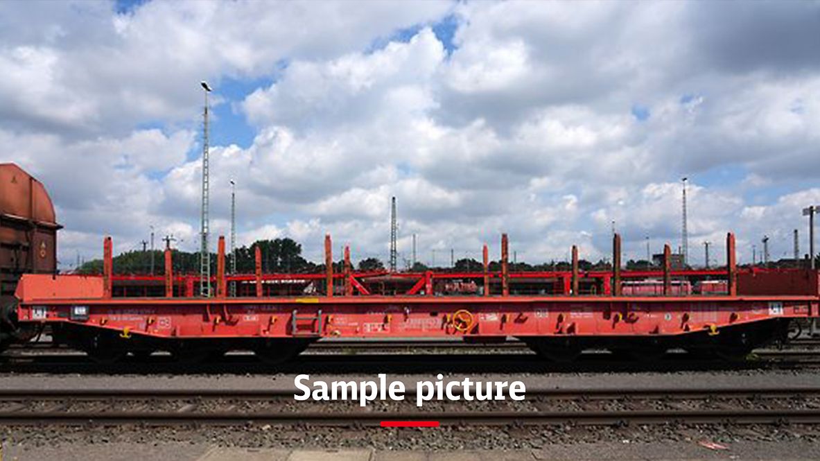
Article: Samm(n)s 695
Flat wagon with six wheelsets, with stanchions, drop ends and folding bolsters, but without drop sides.
Please note: Type is similar to the wagon in the photo. For exact dimensions, please refer to the drawing and the data below.
Technical details
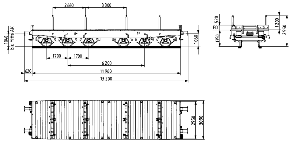
Loading length (mm) | 11,800 |
Loading width (mm) | 2,580 |
Loading area (m2) | 36.0 |
Average tare weight (kg) | 29,000 |
Maximum speed (km/h) | 120 |
International usability | RIV |
Smallest radius of curvature (m) | 75 |
First year of delivery or year of construction of the oldest wagons at this time | 1985 |
Parking brake | With and without parking brake |
Brake type | KE-GP |
Number of brake cylinders (pcs.) | 2 |
Brake cylinder diameter (mm) | 406 |
Type of load-proportional braking | Two-stage, pneumatic, to be changed over manually |
Buffer type: end force (kN) | 590 |
Buffer type: stroke (mm) | 105 |
Buffer head dimensions (mm) | 450 x 340 |
Automatic coupler | Prepared |
Distributor valve type | KE Ra/3.8-2 KSLn 1) |
Individual data
Parabolic springs: stretched length (mm) | 1,200 |
Parabolic springs: number of spring leaves | 4 |
Parabolic springs: spring leaf width (mm) | 120 |
Parabolic springs: spring height (mm) | 155 |
Type and drawing of the bogies | Type 713; 1Fwg900.0.04.000.713 |
Parabolic springs: load capacity (kN) | 20 |
Load limits
Average tare weight 29.0 t
With and without parking brake
A | B1 | B2 | C2 | C4 | D2 | D3 | D4 | ||
|---|---|---|---|---|---|---|---|---|---|
S | 37.5 t | 37.5 t | 55.5 t | 55.5 t | 64.5 t | 55.5 t | 66.5 t | 76.5 t | |
120 |
DB | CE |
|---|---|
100 | 77.0 t |
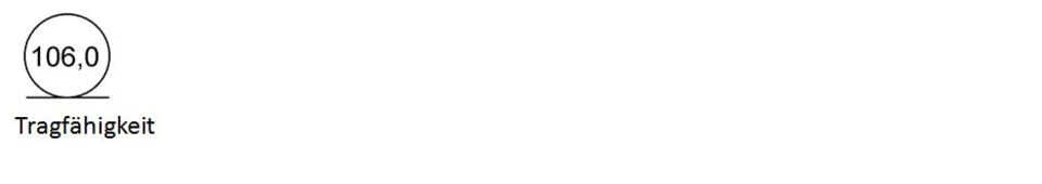
Concentrated loads
m | Spread over the support length | On two baseplates | |
|---|---|---|---|
a-a | 2.0 | 72.0 | 101.0 |
b-b | 3.0 | 90.0 | 106.0 |
c-c | 5.0 | 106.0 | 106.0 |
d-d | 8.5 | 106.0 | 78.0 |
Concentrated loads
m |
|---|
Additional information:
The vehicle is mainly intended for transporting slabs. Four bolsters also enable long material and other bulky goods to be loaded. Lashing rings are recessed in the floor on each side. There are also a sufficient number of lashing rings on the side solebars. Four pockets are built in to accommodate a cover. The floor boards above them may need to be removed accordingly.
The welded structure of the underframe is mainly made of rolled steel sections in S355J2G3 grade steel. The side solebars are connected to each other via pivot bolsters, crossbearers and front-end components. The underframe front end consists of sheet metal and folded sections in S355J2G3 grade steel. Its structure is the same as the Samms 709. The floor consists of 70 mm thick pine planks.
The wagon is equipped with drop ends, four bolsters and eight removable stanchions. The bolsters, stanchions, stanchion mounts, safety devices and storage compartments in the side solebar have been adopted from the Samms 709.1) Consisting of:
- 1 control valve KE 0a/3.8 KSLn 6" c
- 2 pressure transformers Du 111/D
- 1 beam KE No. 5.
Steps, handles, cable hooks and signal supports are designed in accordance with the provisions of the UIC Code.
The non-continuous draw gear consists of a screw coupler, coupling hook and Ringfeder draw gear type 540.
The floor height above top of rail is as follows:
- Wagon No. 485 8 000-9 (first prototype): 1,350 mm
- Wagon No. 485 8 001-7 (second prototype): 1,300 mm
The second prototype also has supports under the headstock, four bearings for the holding pins of the coil stillages and trapezoidal instead of parabolic springs.
All data provided without any guarantee of correctness or completeness.
 Go
Go