Article: Hiirrs-tt 325
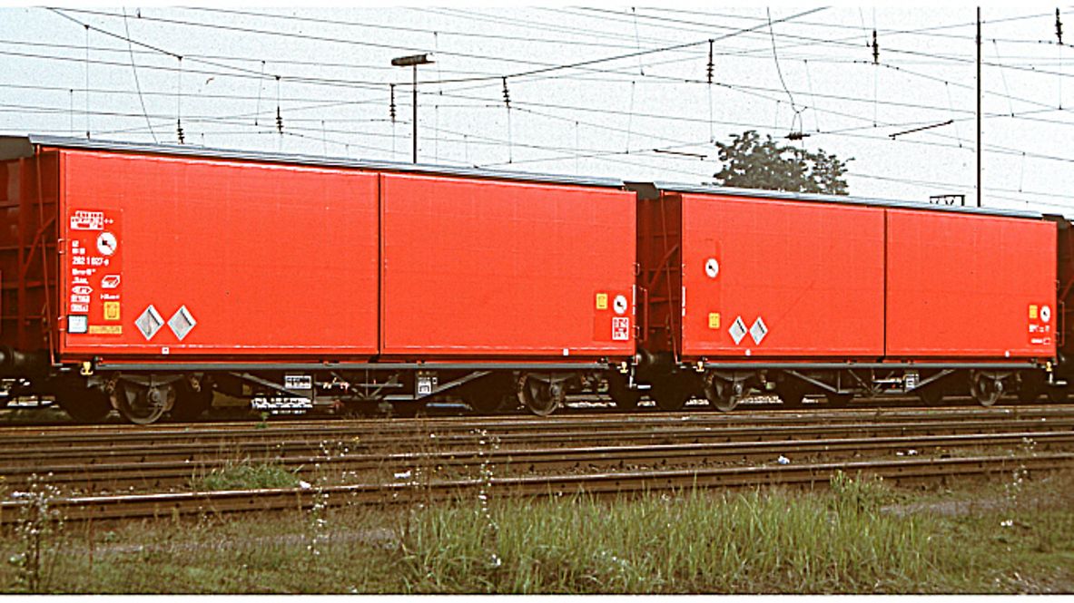
Two-part, permanently coupled freight wagon unit with two-part sliding walls with tarpaulin cover and a lockable partition wall for each single freight wagon.
Please note: Type is similar to the wagon in the photo. For exact dimensions, please refer to the drawing and the data below.
Technical details
Loading width (mm) | 2,590 |
Loading height (mm) | 3,050 |
Loading area (m2) | 2 x 33.0 |
Loading space (m3) | 2 x 100.5 |
Average tare weight (kg) | 32,000 |
Maximum speed (km/h) | 120 |
Smallest radius of curvature (m) | 135 |
First year of delivery or year of construction of the oldest wagons at this time | 1998 |
Conversion year | 2001 (from Hbis-tt 293) |
Parking brake | Without parking brake |
Brake type | KE-GP-A |
Brake cylinder diameter (mm) | 255/300 |
Type of load-proportional braking | Stepless, independent, pneumatic |
Buffer type: end force (kN) | 590 |
Buffer type: stroke (mm) | 105 |
Automatic coupler | Prepared |
Distributor valve type | 2 x KE 2adSL-ALD |
Individual data
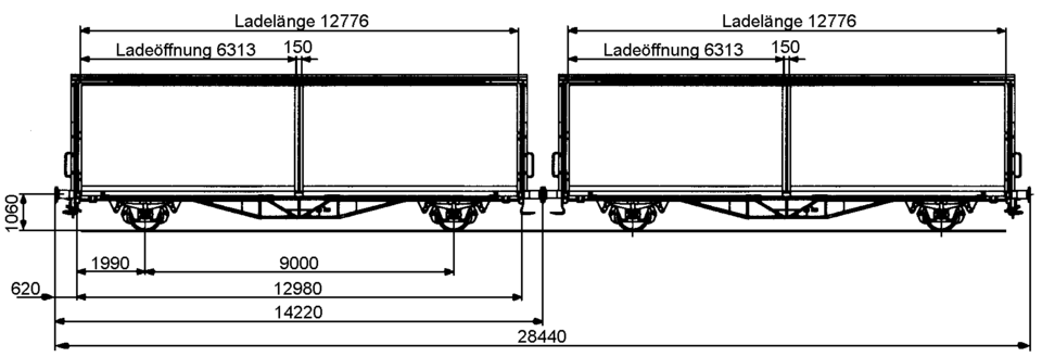
Side wall openings: width (mm) | 6,313 |
Side wall openings: height (mm) | 3,050 |
Running gear as per drawing | 2Fwg295.0.02.000.001 |
Buffer head diameter (mm) | 450 |
Loading length without partitions (mm) | 12,776 |
Loading length with partitions (mm) | 12,632 |
Clearance (mm) | 3,035 |
Number of brake cylinders per element (pcs.) | 1 (double brake cylinder) |
Load limits
Tare weight > 31.5 t ≤ 32.0 t
Without parking brake
A | B1 | B2 | C | ||
|---|---|---|---|---|---|
S | 32.0 t | 40.0 t | 40.0 t | 48.0 t | |
120 |
Additional information:
The wagon unit consists of two permanently coupled Hbis-tt 293, which cannot be separated during operation. For travel on curved tracks <135 m, the permanent coupler can be "made long" so that curved tracks with a radius of up to 75 m can be travelled on. The main brake pipe is connected at the fixed coupling point by a continuous, raised brake hose connection (without brake shut-off cocks and coupling heads).
The wagon unit is intended for transporting moisture-sensitive goods, in particular automotive parts in stillages. It is constructed according to reference profile G2 (EBO), but exceeds this reference profile in the exterior roof area. It can therefore only be used on codified routes with profile P/C 400 and larger. An exemption exists for this in accordance with Section 22 of the EBO. Sidings must be checked for clearance before driving over them.
The wagon has a sliding wall system that is guided at the top and runs on rollers at the bottom. During the opening and closing process, the wall is guided parallel to the wagon body. The locking system corresponds to that of the Hbbi(ll)ns 305/306. The actuating devices for the sliding walls are located on the end walls. The sliding walls have a lightweight design and consist of a frame made of steel sections, folded sheet metal and roof bows, as well as a tarpaulin cover.
The underframe and floor have been adopted unchanged from the Hbills-x 295.
To secure the load, each element of the wagon unit has a lockable partition at one end of the wagon, which can be moved and locked up to 1 m from the end wall. There are 15 mm high stop bars on the long sides of the floor to centre the cargo. The distance between the stop bars is 2,590 mm.
All data provided without any guarantee of correctness or completeness.
 Go
Go