Article: Habins 347
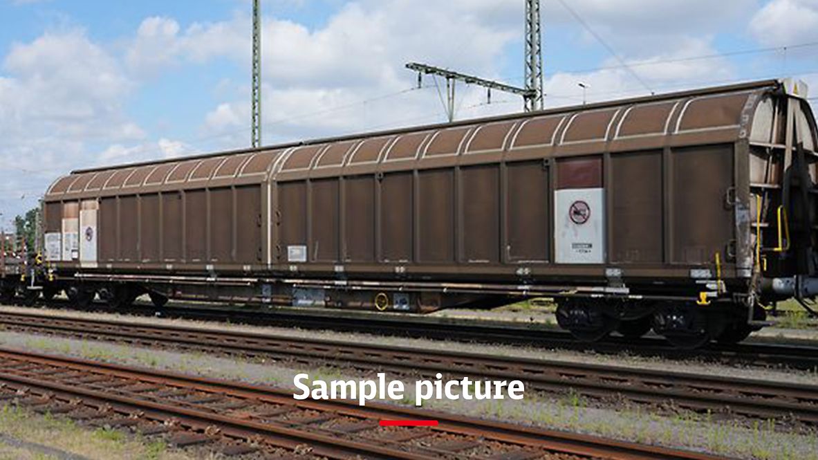
Freight wagon with four wheelsets and two-part aluminium sliding walls.
For delicate loads: these high-capacity wagons are equipped with sliding walls that can be moved by a single person. When open, half of the wagon loading area can be accessed from both sides.
This allows the wagon to be loaded and unloaded using forklift trucks either from a platform or from ground level.
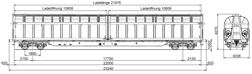
Please note: Type is similar to the wagon in the photo. For exact dimensions, please refer to the drawing and the data below.
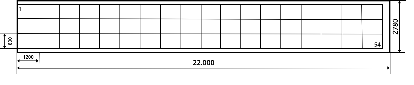
Pallet stowage plan:
Technical details
Loading length (mm) | 21,976 |
Loading width (mm) | 2,780 |
Loading area (m2) | 61.1 |
Loading space (m3) | 164.4 |
Average tare weight (kg) | 27,000 |
Maximum speed (km/h) | 120 |
International usability | RIV |
Smallest radius of curvature (m) | 60 |
First year of delivery or year of construction of the oldest wagons at this time | 1997 |
Parking brake | Without parking brake |
Brake type | KE-GP-A |
Number of brake cylinders (pcs.) | 2 |
Brake cylinder diameter (mm) | 406 |
Type of load-proportional braking | Stepless, automatic |
Buffer type | Category C, 70 kJ |
Buffer head dimensions (mm) | 550 x 340 |
Automatic coupler | Prepared |
Individual data
Side wall openings: width (mm) | 10,808 |
Side wall openings: height (mm) | 2,800 |
Type of the control apparatus | KERD 126 KSLN |
Load limits
Average tare weight 27.0 t
Without parking brake
A | B | C | D | ||
|---|---|---|---|---|---|
S | 37.0 t | 45.0 t | 55.0 t | 63.0 t | |
120 |
Additional information:
The sliding-wall wagon with covered ridge girder is suitable for transporting weather-sensitive, large-volume and palletised loads and handling them quickly and economically, as well as ensuring adequate load protection for specific users. The wagon has two fixed end walls, a fixed central portal and a narrow ridge girder covered by the roof sections, as well as two sliding wall sections with angled roof halves on each side of the wagon.
The underframe and the wagon body are made of a steel construction using sections, welded beams and folded sheet metal.
The body of the vehicle is formed by two fixed end walls, a fixed central portal, a narrow ridge girder and four aluminium sliding wall sections that can be swung out and cover the roof ridge girder. The end walls serve to secure the load in the event of impacts with the buffers and are dimensioned accordingly.
Each sliding wall has two running gear supports with a guide roller running gear in the underframe area. The castors are unloaded when the walls are closed. The sliding walls are fitted on the inside with a 25 mm thick protective wooden cladding in the lower area at a height of up to 420 mm above the top of floor.
The swivel mechanism of the sliding wall sections is actuated from the corresponding end of the wagon, with each sliding wall section having a separate swivel mechanism. Each swivel mechanism consists of the upper and the lower swivelling shaft parallel to the longitudinal axis of the wagon; these shafts are connected to the actuating system via rods on the end face of the wagon. The sliding walls can be actuated from the top of rail as well as from a side-loading platform. In all swivel and slide positions, the sliding wall sections are secured against lifting out. A device to protect against operator error is built in.The floor consists of a supporting lattice structure made of hot-rolled solebars, curved crossbearers and 30 mm thick plywood elements. The plywood elements cover the entire loading area, with the exception of the draw gear box and the upper flange of the headstock. The corners of the plywood elements are not sharp.
The photo shows a type 344 wagon.
All data provided without any guarantee of correctness or completeness.
 Go
Go