Article: Falns 181
Open bulk freight wagons with bulk gravity unloading, hydraulic flap-closing system and four wheelsets. Suitable for heavy bulk goods.
Well-coordinated: all four flaps are opened and closed simultaneously by actuating a control valve either from the wagon platform or from the bunker gantry using a special long-handled carriage key.
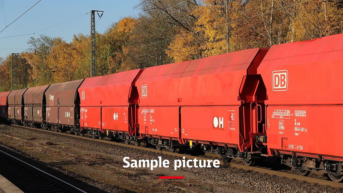
Please note: Type is similar to the wagon in the photo. For exact dimensions, please refer to the data below.
Technical details
Loading space (m3) | 86.0 |
Average tare weight (kg) | 24,000 |
Maximum speed (km/h) | 120 |
International usability | G2 |
Smallest radius of curvature (m) | 75 |
First year of delivery or year of construction of the oldest wagons at this time | 2010 |
Parking brake | With and without parking brake |
Brake type | KE-GP-A (K) |
Number of brake cylinders (pcs.) | 1 |
Brake cylinder diameter (mm) | 406 |
Type of load-proportional braking | Automatic |
Buffer type | Category A, min. 32 kJ |
Buffer head dimensions (mm) | 450 x 340 |
Automatic coupler | Prepared |
Distributor valve type | KE2dvSL-ALB/d148/1 |
Individual data
Side flap deflection – largest (mm) | 4,300 |
Screw coupler, reinforced (kN) | 1,350 |
Draw hook, reinforced (kN) | 1,500 |
Load limits
Tare weight > 23.5 t ≤ 24.0 t
With and without parking brake
A | B1 | B2 | C2 | C3 | C4 | D2 | D3 | D4 | ||
|---|---|---|---|---|---|---|---|---|---|---|
S | 38.5 t | 38.5 t | 48.0 t | 56.0 t | 58.0 t | 58.0 t | 56.0 t | 66.0 t | 66.0 t | |
120 |
DB | CM2 | CM3 | CM4 |
|---|---|---|---|
100 | 56.0 t | 60.0 t | 60.0 t |
Additional information:
It complies with the construction regulations according to TSI WAG Appendix YY and EN 12663. Unless explicitly stated otherwise in these specifications, this wagon is made of S355J2 according to EN 10025 and DBS 918 002-01. For material thicknesses below 6 mm, added copper is taken into account. The wagon body is a composite construction. The wagon body (the area that comes into contact with the cargo) including the flap plates is made of stainless steel material X2CrNi12 according to EN 10088 – material no. 1.4003.
A metallic sealing strip made of Cr-Ni steel (X2CrNi12 material 1.4003) is fitted for sealing the bottom of the flaps. In order to stop cargo residue from rat holing, corners have been avoided in the loading space. Corresponding fillets or corner plates have been installed.
The wagon body is designed for an axle load of 23.5 t.The wagon is equipped with an energy-self-sufficient hydraulic accumulator (B&S) with a higher safety level, which consists of the following main components:
- Wheelset pump
- Oil tank with valves
- Piston accumulator with 10.0 l effective volume
- 1 actuating cylinder
- 1 locking cylinder
The wheelset pump delivers pressurised oil to the piston accumulator (27 l) When the max. operating pressure of approx. 220 bar is reached, the pump is switched to unpressurised circulation. The accumulator charge state be seen on the sight glass of the oil tank. If the hydraulic system is switched, e.g. via the switching shaft, pressurised oil flows via the control valve to/through the locking cylinder to the actuating cylinder. The flaps are opened or closed (open/close three times). All four flaps are opened and closed simultaneously.
Retrofitting is possible for an automatic control. The oil and gas pressure can be checked via Minimess ports in the system. Actuation is via a carriage key from the bunker gantry or from the platform of the wagon via levers located on the end wall of the wagon.
A hydraulically powered camlock shaft closing mechanism is installed in this wagon. The actuating cylinder, which is located in the centre of the wagon, powers the camlock shafts via drive shafts and guide rods. The camlock shafts are mounted in single-shear hook bearings as well as in split Elges spherical plain bearings and have five camlocks for each flap. The drive is designed in such a way that the bottom side of the cylinder is pressurised with hydraulic oil when closing.
When closed, the closing mechanism has a past top dead centre position as well as an additional mechanical lock. This locking (unlocking) motion is actuated by a damped hydraulic cylinder and a return spring. Coupled to this lock is an indicator that actuates yellow signal backgrounds via a rod. These indicate proper locking when swivelled in.
All data provided without any guarantee of correctness or completeness.
 Go
Go